th-twig
To test the cooling system directly at the indoor unit without a thermostat or thermostat wiring, you need to jump the low-voltage terminal strip on the furnace integrated control board. Your International Comfort Products (ICP) N9MSE1202420A2 is a 95% AFUE single-stage gas furnace; testing the AC requires a simultaneous call for both the indoor blower fan and the outdoor condensing unit. [1, 2, 3]
1. Gain Control Board Access
- Turn off the main electrical power to the furnace using the service switch or circuit breaker.
- Remove the furnace blower access door to expose the integrated control board.
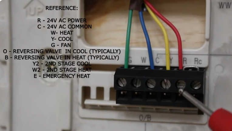
- Locate the low-voltage terminal block labeled R, C, G, Y, W. [4, 5, 6, 7]
2. Connect Your Jumper Wires
- Use an insulated alligator clip jumper wire to bridge the R (24VAC hot) terminal to the Y (cooling call) terminal.
- Use a second jumper wire to bridge the R terminal to the G (indoor fan) terminal.
- Note: You must jumper both Y and G simultaneously on this model to force both the indoor blower motor and the outdoor compressor contactor to pull in together. [3, 7, 8, 9, 10]
3. Verify the Condenser Splice
- Ensure that the two field-installed low-voltage wires running from the outdoor condenser unit are securely connected to the Y and C (common) terminals on this board. [7, 11]
- If there are no field wires landed on the control board at all, you will need to wire your jumper directly from R to the condenser’s contactor coil wire, while the other side of the contactor coil lands on C. [7, 12]
4. Energize and Observe
- Securely tape down or manually depress the furnace door safety switch to allow the 120V line voltage back into the system.
- Restore the main electrical power.
- The indoor blower should kick on immediately, and the outdoor compressor/condenser fan should ramp up. [5, 8, 13, 14, 15]
5. Shut Down Safely
- When testing is complete, disconnect the main power source first before removing your jumper wires.
- Removing jumpers under power can spark and easily pop the low-voltage blade fuse (typically a 3A or 5A automotive fuse) on the ICP control board. [8, 9]
✅ Verification
The cooling circuit will successfully activate when R is jumpered directly to both Y and G while the outdoor contactor loop is completed across Y and C. [3, 7] If the system fails to start with these jumpers in place, let me know:
- Is the control board displaying any flashing LED diagnostic fault codes?
- Are you reading 24VAC across R and C using your multimeter?
- Is the outdoor contactor physically pulling in, or is it silent? [12, 14, 16]
I can walk you through checking the transformer or diagnosing a low-voltage short based on what you find!
[1] https://www.shareddocs.com [2] https://www.partstown.com [3] https://www.youtube.com [4] https://www.justanswer.com [5] https://www.youtube.com [6] https://www.shareddocs.com [7] https://www.youtube.com [8] https://www.justanswer.com [9] https://www.appliancepartspros.com [10] https://www.youtube.com [11] https://www.justanswer.com [12] https://www.youtube.com [13] https://www.shareddocs.com [14] https://www.youtube.com [15] https://www.nordichomeinspection.com [16] https://www.manualslib.com